Circuit analysisThe heart of this circuit is a CD4017 (IC1), CMOS counter with decoded output. On each pulse received on its clock input, this IC drives high the next output (all the other are driven low).
 Output 0, 1 and 2 drives red, green and blue LEDs through transistors Q2, Q3, Q4 (emitter follower is used to avoid the need of a base resistor). During the first three phases, output 4 is driven low and provide ground reference for photo-resistor R8: the RCX can read light level reflected in each color. In phase 4 photo-resistor is no longer grounded, value returned to RCX is maximum (note the 1 Mohm resistor paralleled with R8 to prevent maximum value to be reached in phases 1/2/3). RCX can detect this special condition and synchronize its readings to CD4017 state.
 Output 0, 1 and 2 drives red, green and blue LEDs through transistors Q2, Q3, Q4 (emitter follower is used to avoid the need of a base resistor). During the first three phases, output 4 is driven low and provide ground reference for photo-resistor R8: the RCX can read light level reflected in each color. In phase 4 photo-resistor is no longer grounded, value returned to RCX is maximum (note the 1 Mohm resistor paralleled with R8 to prevent maximum value to be reached in phases 1/2/3). RCX can detect this special condition and synchronize its readings to CD4017 state.
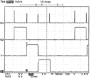
The oscilloscope hard-copy shows clock pulse on top trace, output 1/2/3 below.
 To generate a clock pulse, you have to switch from active sensor mode (sensor voltage is higher than Zener D4 threshold, Q1 is conducting, clock input is low) to passive sensor mode (sensor voltage is lower than D4 threshold, Q1 is blocked, clock input is high) and back to active sensor. C1 filters out short power supply pulses occuring in active mode evey 3ms while RCX reads value.
 To generate a clock pulse, you have to switch from active sensor mode (sensor voltage is higher than Zener D4 threshold, Q1 is conducting, clock input is low) to passive sensor mode (sensor voltage is lower than D4 threshold, Q1 is blocked, clock input is high) and back to active sensor. C1 filters out short power supply pulses occuring in active mode evey 3ms while RCX reads value.
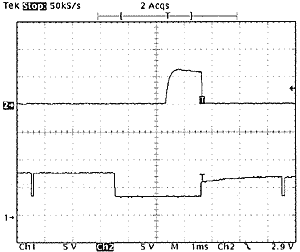
The oscilloscope hard-copy shows clock pulse on top trace, sensor voltage on bottom trace showing 2 short reading pulses and wide command pulse generated by sensor mode switching.
When reaching step 5, CD4017 activates D04 and reset itself to step1 through R4/C3. This RC network delays reset pulse well after clock transition: without it, the current rush of the LED, coupled through power supply, modifies clock threshold and CD4017 goes directly to step 2...
When reaching step 5, CD4017 activates D04 and reset itself to step1 through R4/C3. This RC network delays reset pulse well after clock transition: without it, the current rush of the LED, coupled through power supply, modifies clock threshold and CD4017 goes directly to step 2...
Power supply is rectified by D1 and filtered by C2. As in my other sensors, I keep on with single diode instead of full bridge to minimize components count (3 diodes instead of 8!) but as you can see I built the breadboard with a full bridge module I constructed to ease my prototypes.


No comments:
Post a Comment