Technologies
There are a variety of touchscreen technologies:
Resistive
Main article: Resistive touchscreen
A resistive touchscreen panel is composed of several layers, the most important of which are two thin, electrically conductive layers separated by a narrow gap. When an object, such as a finger, presses down on a point on the panel's outer surface the two metallic layers become connected at that point: the panel then behaves as a pair of voltage dividers with connected outputs. This causes a change in the electrical current, which is registered as a touch event and sent to the controller for processing. The cover sheet consists of a hard outer surface with a coated inner side. When the outer layer is touched it causes the conductive layers to touch creating a signal that the analog controller can interpret and determine what the user wants to be done. Resistive touch is used in restaurants, factories and hospitals due to its high resistance to liquids and contaminants. A major benefit of resistive touch technology is it is extremely cost-effective. One disadvantage of resistive technology is its vulnerability of being damaged by sharp objects.
Surface acoustic wave
Main article: Surface acoustic wave
Surface acoustic wave (SAW) technology uses ultrasonic waves that pass over the touchscreen panel. When the panel is touched, a portion of the wave is absorbed. This change in the ultrasonic waves registers the position of the touch event and sends this information to thecontroller for processing. Surface wave touchscreen panels can be damaged by outside elements. Contaminants on the surface can also interfere with the functionality of the touchscreen.[10]
Capacitive
Main article: Capacitive sensing
A capacitive touchscreen panel consists of an insulator such as glass, coated with a transparentconductor such as indium tin oxide (ITO).[11][12] As the human body is also an electrical conductor, touching the surface of the screen results in a distortion of the screen's electrostaticfield, measurable as a change in capacitance. Different technologies may be used to determine the location of the touch. The location is then sent to the controller for processing. Unlike aresistive touchscreen, one cannot use a capacitive touchscreen through most types of electrically insulating material, such as gloves; one requires a special capacitive stylus, or a special-application glove with finger tips that generate[citation needed] static electricity. This disadvantage especially affects usability in consumer electronics, such as touch tablet PCs and capacitive smartphones in cold weather.
Surface capacitance
In this basic technology, only one side of the insulator is coated with a conductive layer. A small voltage is applied to the layer, resulting in a uniform electrostatic field. When a conductor, such as a human finger, touches the uncoated surface, a capacitor is dynamically formed. The sensor's controller can determine the location of the touch indirectly from the change in the capacitance as measured from the four corners of the panel. As it has no moving parts, it is moderately durable but has limited resolution, is prone to false signals from parasitic capacitive coupling, and needs calibration during manufacture. It is therefore most often used in simple applications such as industrial controls andkiosks.[13]
Projected capacitance
Projected Capacitive Touch (PCT) technology is a capacitive technology which permits more accurate and flexible operation, by etching the conductive layer. An X-Y grid is formed either by etching a single layer to form a grid pattern of electrodes, or by etching two separate, perpendicular layers of conductive material with parallel lines or tracks to form the grid (comparable to the pixel grid found in many LCDdisplays).
The greater resolution of PCT allows operation without direct contact, such that the conducting layers can be coated with further protective insulating layers, and operate even under screen protectors, or behind weather and vandal-proof glass. Due to the top layer of a PCT being glass, PCT is a more robust solution versus resistive touch technology. Depending on the implementation, an active or passive stylus can be used instead of or in addition to a finger. This is common with point of sale devices that require signature capture. Gloved fingers may or may not be sensed, depending on the implementation and gain settings. Conductive smudges and similar interference on the panel surface can interfere with the performance. Such conductive smudges come mostly from sticky or sweaty finger tips, especially in high humidity environments. Collected dust, which adheres to the screen due to the moisture from fingertips can also be a problem. There are two types of PCT: Self Capacitance and Mutual Capacitance.
A PCT screen consists of an insulator such as glass or foil, coated with a transparent conductor – sensing (Copper, ATO, Nanocarbon or ITO). As the human finger (is also a conductor) touching the surface of the screen results in a distortion of the local electrostatic field, measurable as a change in capacitance.Now PCT used mutual capacitance, which is the more common projected capacitive approach and makes use of the fact that most conductive objects are able to hold a charge if they are very close together. If another conductive object, in this case a finger, bridges the gap, the charge field is interrupted and detected by the controller. All PCT touch screens are made up of an electrode - a matrix of rows and columns. The capacitance can be changed at every individual point on the grid (intersection). It can be measured to accurately determine the exactly touch location. All projected capacitive touch (PCT) solutions have three key features in common: • Sensor as matrix of rows and columns• Sensor lies behind the touch surface • Sensor does not use any moving parts.[14]
Mutual capacitance
In mutual capacitive sensors, there is a capacitor at every intersection of each row and each column. A 16-by-14 array, for example, would have 224 independent capacitors. A voltage is applied to the rows or columns. Bringing a finger or conductive stylus close to the surface of the sensor changes the local electrostatic field which reduces the mutual capacitance. The capacitance change at every individual point on the grid can be measured to accurately determine the touch location by measuring the voltage in the other axis. Mutual capacitance allowsmulti-touch operation where multiple fingers, palms or styli can be accurately tracked at the same time.
Self-capacitance
Self-capacitance sensors can have the same X-Y grid as mutual capacitance sensors, but the columns and rows operate independently. With self-capacitance, the capacitive load of a finger is measured on each column or row electrode by a current meter. This method produces a stronger signal than mutual capacitance, but it is unable to resolve accurately more than one finger, which results in "ghosting", or misplaced location sensing.
Infrared
An infrared touchscreen uses an array of X-Y infrared LED and photodetector pairs around the edges of the screen to detect a disruption in the pattern of LED beams. These LED beams cross each other in vertical and horizontal patterns. This helps the sensors pick up the exact location of the touch. A major benefit of such a system is that it can detect essentially any input including a finger, gloved finger, stylus or pen. It is generally used in outdoor applications and point of salesystems which can't rely on a conductor (such as a bare finger) to activate the touchscreen. Unlike capacitive touchscreens, infrared touchscreens do not require any patterning on the glass which increases durability and optical clarity of the overall system.
Optical imaging
This is a relatively modern development in touchscreen technology, in which two or more image sensors are placed around the edges (mostly the corners) of the screen. Infrared back lights are placed in the camera's field of view on the other side of the screen. A touch shows up as a shadow and each pair of cameras can then be pinpointed to locate the touch or even measure the size of the touching object (see visual hull). This technology is growing in popularity, due to its scalability, versatility, and affordability, especially for larger units.
Dispersive signal technology
Introduced in 2002 by 3M, this system uses sensors to detect the Piezoelectricity in the glass that occurs due to a touch. Complex algorithms then interpret this information and provide the actual location of the touch.[15] The technology claims to be unaffected by dust and other outside elements, including scratches. Since there is no need for additional elements on screen, it also claims to provide excellent optical clarity. Also, since mechanical vibrations are used to detect a touch event, any object can be used to generate these events, including fingers and stylus. A downside is that after the initial touch the system cannot detect a motionless finger.
Acoustic pulse recognition
This system, introduced by Tyco International's Elo division in 2006, The key to the invention is that a touch at each position on the glass generates a unique sound. Four tiny transducers attached to the edges of the touchscreen glass pick up the sound of the touch. The sound is then digitized by the controller and compared to a list of prerecorded sounds for every position on the glass. The cursor position is instantly updated to the touch location. APR is designed to ignore extraneous and ambient sounds, as they do not match a stored sound profile. APR differs from other attempts to recognize the position of touch with transducers or microphones, as it uses a simple table lookup method rather than requiring powerful and expensive signal processing hardware to attempt to calculate the touch location without any references [16] . The touchscreen itself is made of ordinary glass, giving it good durability and optical clarity. It is usually able to function with scratches and dust on the screen with good accuracy. The technology is also well suited to displays that are physically larger. As with the Dispersive Signal Technology system, after the initial touch, a motionless finger cannot be detected. However, for the same reason, the touch recognition is not disrupted by any resting objects.


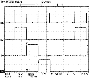
 Output 0, 1 and 2 drives red, green and blue LEDs through transistors Q2, Q3, Q4 (emitter follower is used to avoid the need of a base resistor). During the first three phases, output 4 is driven low and provide ground reference for photo-resistor R8: the RCX can read light level reflected in each color. In phase 4 photo-resistor is no longer grounded, value returned to RCX is maximum (note the 1 Mohm resistor paralleled with R8 to prevent maximum value to be reached in phases 1/2/3). RCX can detect this special condition and synchronize its readings to CD4017 state.
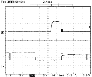
 To generate a clock pulse, you have to switch from active sensor mode (sensor voltage is higher than Zener D4 threshold, Q1 is conducting, clock input is low) to passive sensor mode (sensor voltage is lower than D4 threshold, Q1 is blocked, clock input is high) and back to active sensor. C1 filters out short power supply pulses occuring in active mode evey 3ms while RCX reads value.


