COUNTER

Powered By Blogger

Monday, October 3, 2011

Touchscreen


Technologies

There are a variety of touchscreen technologies:


Resistive

resistive touchscreen panel is composed of several layers, the most important of which are two thin, electrically conductive layers separated by a narrow gap. When an object, such as a finger, presses down on a point on the panel's outer surface the two metallic layers become connected at that point: the panel then behaves as a pair of voltage dividers with connected outputs. This causes a change in the electrical current, which is registered as a touch event and sent to the controller for processing. The cover sheet consists of a hard outer surface with a coated inner side. When the outer layer is touched it causes the conductive layers to touch creating a signal that the analog controller can interpret and determine what the user wants to be done. Resistive touch is used in restaurants, factories and hospitals due to its high resistance to liquids and contaminants. A major benefit of resistive touch technology is it is extremely cost-effective. One disadvantage of resistive technology is its vulnerability of being damaged by sharp objects.

Surface acoustic wave

Surface acoustic wave (SAW) technology uses ultrasonic waves that pass over the touchscreen panel. When the panel is touched, a portion of the wave is absorbed. This change in the ultrasonic waves registers the position of the touch event and sends this information to thecontroller for processing. Surface wave touchscreen panels can be damaged by outside elements. Contaminants on the surface can also interfere with the functionality of the touchscreen.[10]

Capacitive


Capacitive touchscreen of a mobile phone
A capacitive touchscreen panel consists of an insulator such as glass, coated with a transparentconductor such as indium tin oxide (ITO).[11][12] As the human body is also an electrical conductor, touching the surface of the screen results in a distortion of the screen's electrostaticfield, measurable as a change in capacitance. Different technologies may be used to determine the location of the touch. The location is then sent to the controller for processing. Unlike aresistive touchscreen, one cannot use a capacitive touchscreen through most types of electrically insulating material, such as gloves; one requires a special capacitive stylus, or a special-application glove with finger tips that generate[citation needed] static electricity. This disadvantage especially affects usability in consumer electronics, such as touch tablet PCs and capacitive smartphones in cold weather.

Surface capacitance

In this basic technology, only one side of the insulator is coated with a conductive layer. A small voltage is applied to the layer, resulting in a uniform electrostatic field. When a conductor, such as a human finger, touches the uncoated surface, a capacitor is dynamically formed. The sensor's controller can determine the location of the touch indirectly from the change in the capacitance as measured from the four corners of the panel. As it has no moving parts, it is moderately durable but has limited resolution, is prone to false signals from parasitic capacitive coupling, and needs calibration during manufacture. It is therefore most often used in simple applications such as industrial controls andkiosks.[13]

Projected capacitance

Projected Capacitive Touch (PCT) technology is a capacitive technology which permits more accurate and flexible operation, by etching the conductive layer. An X-Y grid is formed either by etching a single layer to form a grid pattern of electrodes, or by etching two separate, perpendicular layers of conductive material with parallel lines or tracks to form the grid (comparable to the pixel grid found in many LCDdisplays).
The greater resolution of PCT allows operation without direct contact, such that the conducting layers can be coated with further protective insulating layers, and operate even under screen protectors, or behind weather and vandal-proof glass. Due to the top layer of a PCT being glass, PCT is a more robust solution versus resistive touch technology. Depending on the implementation, an active or passive stylus can be used instead of or in addition to a finger. This is common with point of sale devices that require signature capture. Gloved fingers may or may not be sensed, depending on the implementation and gain settings. Conductive smudges and similar interference on the panel surface can interfere with the performance. Such conductive smudges come mostly from sticky or sweaty finger tips, especially in high humidity environments. Collected dust, which adheres to the screen due to the moisture from fingertips can also be a problem. There are two types of PCT: Self Capacitance and Mutual Capacitance.
A PCT screen consists of an insulator such as glass or foil, coated with a transparent conductor – sensing (Copper, ATO, Nanocarbon or ITO). As the human finger (is also a conductor) touching the surface of the screen results in a distortion of the local electrostatic field, measurable as a change in capacitance.Now PCT used mutual capacitance, which is the more common projected capacitive approach and makes use of the fact that most conductive objects are able to hold a charge if they are very close together. If another conductive object, in this case a finger, bridges the gap, the charge field is interrupted and detected by the controller. All PCT touch screens are made up of an electrode - a matrix of rows and columns. The capacitance can be changed at every individual point on the grid (intersection). It can be measured to accurately determine the exactly touch location. All projected capacitive touch (PCT) solutions have three key features in common: • Sensor as matrix of rows and columns• Sensor lies behind the touch surface • Sensor does not use any moving parts.[14]
Mutual capacitance
In mutual capacitive sensors, there is a capacitor at every intersection of each row and each column. A 16-by-14 array, for example, would have 224 independent capacitors. A voltage is applied to the rows or columns. Bringing a finger or conductive stylus close to the surface of the sensor changes the local electrostatic field which reduces the mutual capacitance. The capacitance change at every individual point on the grid can be measured to accurately determine the touch location by measuring the voltage in the other axis. Mutual capacitance allowsmulti-touch operation where multiple fingers, palms or styli can be accurately tracked at the same time.
Self-capacitance
Self-capacitance sensors can have the same X-Y grid as mutual capacitance sensors, but the columns and rows operate independently. With self-capacitance, the capacitive load of a finger is measured on each column or row electrode by a current meter. This method produces a stronger signal than mutual capacitance, but it is unable to resolve accurately more than one finger, which results in "ghosting", or misplaced location sensing.

Infrared


Infrared sensors mounted around the display watch for a user's touchscreen input on this PLATO V terminal in 1981. The monochromatic plasma display's characteristic orange glow is illustrated.
An infrared touchscreen uses an array of X-Y infrared LED and photodetector pairs around the edges of the screen to detect a disruption in the pattern of LED beams. These LED beams cross each other in vertical and horizontal patterns. This helps the sensors pick up the exact location of the touch. A major benefit of such a system is that it can detect essentially any input including a finger, gloved finger, stylus or pen. It is generally used in outdoor applications and point of salesystems which can't rely on a conductor (such as a bare finger) to activate the touchscreen. Unlike capacitive touchscreens, infrared touchscreens do not require any patterning on the glass which increases durability and optical clarity of the overall system.

Optical imaging

This is a relatively modern development in touchscreen technology, in which two or more image sensors are placed around the edges (mostly the corners) of the screen. Infrared back lights are placed in the camera's field of view on the other side of the screen. A touch shows up as a shadow and each pair of cameras can then be pinpointed to locate the touch or even measure the size of the touching object (see visual hull). This technology is growing in popularity, due to its scalability, versatility, and affordability, especially for larger units.

Dispersive signal technology

Introduced in 2002 by 3M, this system uses sensors to detect the Piezoelectricity in the glass that occurs due to a touch. Complex algorithms then interpret this information and provide the actual location of the touch.[15] The technology claims to be unaffected by dust and other outside elements, including scratches. Since there is no need for additional elements on screen, it also claims to provide excellent optical clarity. Also, since mechanical vibrations are used to detect a touch event, any object can be used to generate these events, including fingers and stylus. A downside is that after the initial touch the system cannot detect a motionless finger.

Acoustic pulse recognition

This system, introduced by Tyco International's Elo division in 2006, The key to the invention is that a touch at each position on the glass generates a unique sound. Four tiny transducers attached to the edges of the touchscreen glass pick up the sound of the touch. The sound is then digitized by the controller and compared to a list of prerecorded sounds for every position on the glass. The cursor position is instantly updated to the touch location. APR is designed to ignore extraneous and ambient sounds, as they do not match a stored sound profile. APR differs from other attempts to recognize the position of touch with transducers or microphones, as it uses a simple table lookup method rather than requiring powerful and expensive signal processing hardware to attempt to calculate the touch location without any references [16] . The touchscreen itself is made of ordinary glass, giving it good durability and optical clarity. It is usually able to function with scratches and dust on the screen with good accuracy. The technology is also well suited to displays that are physically larger. As with the Dispersive Signal Technology system, after the initial touch, a motionless finger cannot be detected. However, for the same reason, the touch recognition is not disrupted by any resting objects.

Wednesday, June 15, 2011

COLOUR SENSOR


    Circuit analysisThe heart of this circuit is a CD4017 (IC1), CMOS counter with decoded output. On each pulse received on its clock input, this IC drives high the next output (all the other are driven low). 

    Output 0, 1 and 2 drives red, green and blue LEDs through transistors Q2, Q3, Q4 (emitter follower is used to avoid the need of a base resistor). During the first three phases, output 4 is driven low and provide ground reference for photo-resistor R8: the RCX can read light level reflected in each color. In phase 4 photo-resistor is no longer grounded, value returned to RCX is maximum (note the 1 Mohm resistor paralleled with R8 to prevent maximum value to be reached in phases 1/2/3). RCX can detect this special condition and synchronize its readings to CD4017 state.
    The oscilloscope hard-copy shows clock pulse on top trace, output 1/2/3 below.

    To generate a clock pulse, you have to switch from active sensor mode (sensor voltage is higher than Zener D4 threshold, Q1 is conducting, clock input is low) to passive sensor mode (sensor voltage is lower than D4 threshold, Q1 is blocked, clock input is high) and back to active sensor. C1 filters out short power supply pulses occuring in active mode evey 3ms while RCX reads value.
    The oscilloscope hard-copy shows clock pulse on top trace, sensor voltage on bottom trace showing 2 short reading pulses and wide command pulse generated by sensor mode switching.

    When reaching step 5, CD4017 activates D04 and reset itself to step1 through R4/C3. This RC network delays reset pulse well after clock transition: without it, the current rush of the LED, coupled through power supply, modifies clock threshold and CD4017 goes directly to step 2...
    Power supply is rectified by D1 and filtered by C2. As in my other sensors, I keep on with single diode instead of full bridge to minimize components count (3 diodes instead of 8!) but as you can see I built the breadboard with a full bridge module I constructed to ease my prototypes.

Tuesday, June 7, 2011

Sunday, October 31, 2010

PROTEIN MEMORY

PHOTOCYCLE OF BACTERIORHODOSPIN
Protein based memory use protein seen in halobacteriumhaobium for storage of data.On exposure to laser these protein changes it state.These stable states are used for the storage of binary data.On exposure to red laser they changes to O state which is equivalent to binary 0.When exposed to green laser it changes to P state it is eqivalent to binary 1.these two stable states are used for storing data in binary form.Only O state absorb red light,this is used for data reading.Blue laser will bring the protein to ground state this is used for data erasing.Protein memory can be produced in large quantity and is stable at hgh temperature.A cube 1.6cm dimension can store upto 16gb data.

Friday, October 8, 2010

NANOTECHNOLOGY

                               One of the most developing field in this century is nano technology.Nanotechnology can be applied in every field including communication field.Some of the applications of nanotechnology are self cleaning glass,scratch resistant coating,cloathing,antimicrobial bandage.nano carbon tubes can be formed by rolling shhet of carbon.Now reaserch are going on to use this carbon nano tubes in place of transistors in microprocessors

Wednesday, September 29, 2010

Human-Powered Ornithopter

Impossible dream as it seemed to have a human-powered ornithopter flown in the air, as many have failed and yet one have succeeded. Thanks to lightweight carbon fiber and to a Canadian engineering student, who have conquered a dream pondered over by inventors and flight enthusiasts for over a hundred years, flying an ornithopter. (an aircraft that flaps its wings like a bird to sustain forward momentum and some lift). You can watch the record breaking flight just hit the continue link below

Monday, August 30, 2010

Artificial Cornea Offers Long-Term Vision


Patients with impaired vision because of a damaged cornea could soon regain their sight without need of a human donor transplant. Instead, such patients could be aided by an artificial but biosynthetic implant. One such implant has now been tested in patients over two years, and the results are as good as, or even better than, those achieved with donor corneas.

The transparent tissue that covers the surface of the eyes, the cornea, can be damaged by injury, infection, or inflammation, causing the eye to lose much of its ability to refract light and focus images on the retina. Such damage has caused loss of vision in millions of people around the world. The best treatment for cornea damage remains a transplant, but donor corneas are in chronically short supply.

Plastic replacements have been available for decades, but their implantation is still plagued by side effects such as infection and glaucoma. "They remain a last resort option for patients where all other options have failed, including donor transplants," says Joachim Storsberg at the Fraunhofer Institute for Applied Polymer Research in Potsdam, Germany. Storsberg is developing plastic implants but was not involved with the current work.


Wednesday, August 25, 2010

ABS

An anti lock breaking system(ABS) prevents the vechile wheels from locking up while breaking.
ABS ComponentsMain components to an ABS system:


Speed sensors
Pump
Valves
Controller

Speed SensorsThe ABS needs some way of knowing when a wheel is about to lock up. The speed sensors, which are located at each wheel, or in some cases in the differential, provide this information.PumpSince the valve is able to release pressure from the brakes, there has to be some way to put that pressure back. That is what the pump does; when a valve reduces the pressure in a line, the pump is there to get the pressure back up.ValvesThere is a valve in the brake line of each brake controlled by the ABS. On some systems, the valve has three positions:


In position one, the valve is open; pressure from the master cylinder is passed right through to the brake.
In position two, the valve blocks the line, isolating that brake from the master cylinder. This prevents the pressure from rising further should the driver push the brake pedal harder.
In position three, the valve releases some of the pressure from the brake.
ControllerThe controller is a computer in the car. It watches the speed sensors and controls the valves.ABS at WorkThere are many different variations and control algorithms for ABS systems. We will discuss how one of the simpler systems works.
The controller monitors the speed sensors at all times. It is looking for decelerations in the wheel that are out of the ordinary. Right before a wheel locks up, it will experience a rapid deceleration. If left unchecked, the wheel would stop much more quickly than any car could. It might take a car five seconds to stop from 60 mph (96.6 kph) under ideal conditions, but a wheel that locks up could stop spinning in less than a second.
The ABS controller knows that such a rapid deceleration is impossible, so it reduces the pressure to that brake until it sees an acceleration, then it increases the pressure until it sees the deceleration again. It can do this very quickly, before the tire can actually significantly change speed. The result is that the tire slows down at the same rate as the car, with the brakes keeping the tires very near the point at which they will start to lock up. This gives the system maximum braking power.
When the ABS system is in operation you will feel a pulsing in the brake pedal; this comes from the rapid opening and closing of the valves. Some ABS systems can cycle up to 15 times per second

Friday, June 4, 2010

VIOP


Voice over Internet Protocol (VoIP) is a general term for a family of transmission technologies for delivery of voice communications over IP networks such as the Internet or other packet-switched networks. Other terms frequently encountered and synonymous with VOIP are IP telephony, Internet telephony, voice over broadband (VoBB), broadband telephony, and broadband phone.


Internet telephony refers to communications services — voice, facsimile, and/or voice-messaging applications — that are transported via the Internet, rather than the public switched telephone network (PSTN). The basic steps involved in originating an Internet telephone call are conversion of the analog voice signal to digital format and compression/translation of the signal into Internet protocol (IP) packets for transmission over the Internet; the process is reversed at the receiving end.[1]


VOIP systems employ session control protocols to control the set-up and tear-down of calls as well as audio codecs which encode speech allowing transmission over an IP network as digital audio via an audio stream. Codec use is varied between different implementations of VOIP (and often a range of codecs are used); some implementations rely on narrowband and compressed speech, while others support high fidelity stereo codecs

Monday, April 26, 2010

uav


An unmanned aerial vehicle (UAV; also known as a remotely piloted vehicle or RPV, or Unmanned Aircraft System (UAS)) is an aircraft that flies without a human crew on board the aircraft. Their largest uses are in military applications. To distinguish UAVs from missiles, a UAV is defined as a reusable, uncrewed vehicle capable of controlled, sustained, level flight and powered by a jet or reciprocating engine. Therefore, cruise missiles are not considered UAVs, because, like many other guided missiles, the vehicle itself is a weapon that is not reused, even though it is also unmanned and in some cases remotely guided.
There are a wide variety of UAV shapes, sizes, configurations, and characteristics. Historically, UAVs were simple drones[1] (remotely piloted aircraft), but autonomous control is increasingly being employed in UAVs. UAVs come in two varieties: some are controlled from a remote location, and others fly autonomously based on pre-programmed flight plans using more complex dynamic automation systems.
Currently, military UAVs perform reconnaissance as well as attack missions.[2] While many successful drone attacks on militants have been reported, they are also prone to collateral damage and/or erroneous targeting, as with many other weapon types.[1] UAVs are also used in a small but growing number of civil applications, such as firefighting or nonmilitary security work, such as surveillance of pipelines. UAVs are often preferred for missions that are too "dull, dirty, or dangerous" for manned aircraft.

Saturday, April 3, 2010

iPad from Apple


The iPad from Apple Inc. (AAPL-Q235.970.970.41%) scored very well in terms of ease of use and battery life in its first reviews, but it won't obliterate the laptop computer market just yet, according to the New York Times and Wall Street Journal.


Reviewers at both papers said that while the tablet computer, which goes on sale on Saturday, works nicely for Web surfing or consuming media like video and books, it may appeal less to people who need laptops for more heavy duty chores.
The Journal's Walt Mossberg said he prefers the iPad as an e-reader to the popular Kindle e-reader from Amazon.com Inc. (AMZN-Q131.81-3.96-2.92%)


But David Pogue from the New York Times said the device's 1.5 pound weight is too heavy for reading compared to Kindle's 10 ounces. He also griped that “You can't read well in direct sunlight” and “You can't read books from the Apple bookstore on any other machine, not even a Mac or iPhone.”
Both reviewers said they were very impressed with the gadget's battery life as it lasted longer than Apple's impressive claim of 10 hours battery life.


Thursday, April 1, 2010

4G MobileTechnology


4G refers to the fourth generation of cellular wireless standards. It is a successor to 3G and 2G standards. The nomenclature of the generations generally refers to a change in the fundamental nature of the service. The first was the move from analogue (1G) to digital (2G) transmission. This was followed by multi-media support, spread spectrum transmission and at least 200 kbit/s (3G) and now 4G, which refers to all IP packet switched networks, mobile ultra-broadband (gigabit speed) access and multi-carrier transmission.


A 4G system is expected to provide a comprehensive and secure all-IP based solution where facilities such as IP telephony, ultra-broadband Internet access, gaming services and streamed multimedia may be provided to users.


The remainder of this article uses 4G to refer to IMT Advanced (International Mobile Telecommunications Advanced), as defined by ITU-R.


An IMT Advanced cellular system must have target peak data rates of up to approximately 100 Mbit/s for high mobility such as mobile access and up to approximately 1 Gbit/s for low mobility such as nomadic/local wireless access, according to the ITU requirements. Scalable bandwidths up to at least 40 MHz should be provided. [1][2]


The pre-4G technology 3GPP Long Term Evolution (LTE) is often branded "4G", but the first LTE release does not fully comply with the IMT-Advanced requirements. LTE has a theoretical net bitrate capacity of up to 100 Mbit/s in the downlink and 50 Mbit/s in the uplink if a 20 MHz channel is used - and more if Multiple-input multiple-output (MIMO), i.e. antenna arrays, are used. Most major mobile carriers in the United States and several worldwide carriers have announced plans to convert their networks to LTE beginning in 2009. The world's first publicly available LTE-service was opened in the two Scandinavian capitals Stockholm and Oslo on the 14 December 2009, and branded 4G. The physical radio interface was at an early stage named High Speed OFDM Packet Access (HSOPA), now named Evolved UMTS Terrestrial Radio Access (E-UTRA).

Tuesday, March 30, 2010

Teleportation

                                                Teleportation
What is Teleportation ?
The conveyance of persons (esp. of oneself) or things by
psychic power; also in futuristic description, apparently
instantaneous transportation of persons, etc., across
space by advanced technological means.


Probably the best known example is the Star Trek ‘Transporter’.


When it comes to the real thing, teleportation means:

SCIENTISTS WORKING in Australia have "beamed up" a radio signal, in the manner of Captain Kirk.


Scientists at the Australian National University in Canberra say they have been able to teleport a laser beam


from one part of their lab to another. The scientists embedded a radio signal into a laser beam, then disintegrated the beam


and reassembled it a meter away virtually instantaneously. They say the laser beam was destroyed


in the teleportation process, but the radio signal survived.


The group of researchers led by physicist Ping Koy Lam have used quantum entanglement - a phenomenon


that links two light photons created at the same time - to induce the changes affected on one photon in another a meter away.


Ping Koy Lam disassembled laser light at one end of an optical communications system and recreated a replica


elsewhere in his lab. The laser beam didn't survive transportation, but its encoded message did.


Dr Lam told the BBC: "What we have demonstrated here is that we can take billions of photons,


destroy them simultaneously, and then recreate them in another place."


He reckons the system could be used to transport secure data. "It should be possible," he says


"to construct a perfect cryptography system. When two parties want to communicate with one another,


we can enable the secrecy of the communication to be absolutely perfect."


While transporting data may be possible, Lam reckons beaming humans to and fro is still some way off.


1) Measurement of the input "state", followed by


2) Disembodied transport of the state, and then


3) Perfect reconstruction in every detail.


It is not:
1) Instantaneous or faster than light


2) Easy

Sunday, March 28, 2010


SOLID STATE DRIVE

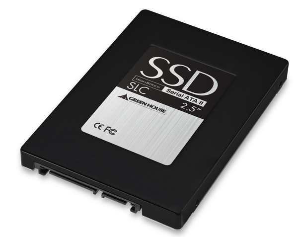
A solid-state drive (SSD) is a data storage device that uses solid-state memory to store persistent data. An SSD emulates a hard disk drive interface, thus easily replacing it in most applications. An SSD using SRAM or DRAM (instead of flash memory) is often called a RAM-drive, not to be confused with a RAM disk. Recently, NAND based flash memory has become the standard for most SSD's.

The original usage of the term "solid-state" (from solid-state physics) refers to the use of semiconductor devices rather than electron tubes but, in the present context, has been adopted to distinguish solid-state electronics from electromechanical devices. With no moving parts, solid-state drives are less fragile than hard disks and are also silent (unless a cooling fan is used); as there are no mechanical delays, they usually enjoy low access time and latency.

Saturday, March 27, 2010


Benefits Of CFL Lighting
25% of a typical home's electricity budget is spent on lighting inefficient incandescent light bulbs. A typical light bulb will cost 5 to 10 times its own cost in electricity during its relatively short lifetime. However there are alternatives. Compact Fluorescent Lights are miniature versions of full-sized strip flourescent lighting and screw straight into the light fitting.


Efficiency of CFL Bulbs
CFL bulbs are around four times as efficent as incandescent light bulbs and last up to 10 times longer. Therefore a 22 Watt CFL will offer the same amount of light as a 100 Watt incandescent bulb and will last for around five years. Using an 18 Watt CFL in place of a 75 Watt standard light bulb will save over 500 kWh over its lifetime offering savings of around £25 - far in excess of the initial cost of the CFL - and will prevent half a ton of CO2 being pumped into the atmosphere by power stations.


Where can CFL Bulbs be Used
CFLs can be used in almost all locations where incandescent light bulbs are used. However the lifetime of a CFL is reduced greatly when used in applications where the light is frequently switched on and off. Also sometimes they are unsuitable for use with dimmer switches, and they cannot be used as spot lights - they are better for lighting whole rooms.


Disadvantages of CFL Bulbs
CFLs do have their disadvantages - for example the average CFL bulb contains 4mg of toxic Mercury.

Wednesday, March 24, 2010


                                                                LED TV


LED-backlit LCD television (called LED TV by Samsung Electronics, Panasonic,Toshiba, Philips, LG Electronics, ProScan and Vizio and not to be confused with true LED displays) is an LCD TV that uses LED backlighting[1] rather than fluorescent lights used in traditional LCD televisions.

The LEDs can come in two forms, Dynamic RGB LEDs which are positioned behind the panel, or white Edge-LEDs positioned around the rim of the screen which use a special diffusion panel to spread the light evenly behind the screen.[2]

LED Backlighting Techniques
[edit]
RGB Dynamic LEDs

This method of backlighting allows dimming to occur locally creating specific areas of darkness on the screen. This can show truer blacks, whites and PRs at much higher dynamic contrast ratios, at the cost of less detail in small bright objects on a dark background, such as star fields.[3]
[edit]
Edge-LEDs

This method of backlighting allows for LED-backlit TVs to become extremely thin. The light is diffused across the screen by a special panel which produces a uniform color range across the screen.

Sharp also has LED backlighting technology that aligns the LEDs on back of the TV like the RGB Dynamic LED backlight, but it lacks the local dimming of other sets.[4]
[edit]
Differences between LED-backlit and CCFL-backlit LCD displays

LED-backlit LCD TVs differ from conventional CCFL-backlit LCD TVs in the following:
They can produce an image with greater dynamic contrast compared with CCFL-backlit LCD TVs.[5]
With Edge-LED lighting they can be extremely slim. Current models on the market can be less than one inch thick.[5]
They can offer a wider color gamut, especially when RGB-LED backlighting is used.[5]
Lesser environmental pollution on disposal.[5]
Higher cost due to current market product placement.[5]
[edit]
Technology

TV manufacturers can use an LED backlight instead of the standard Cold Cathode Fluorescent Lamps (LCD-CCFL) used in most LCD televisions. It is important to distinguish this method of simply backlighting a conventional LCD panel, from a hypothetical true LED display, or an OLED display. LCD-based televisions described as 'LED TVs' are vastly different from self-illuminating OLED, OEL or AMOLED display technologies. In terms of the use of the term 'LED TV' in the UK, the ASA (Advertising Standards Authority) has made it clear in prior correspondence that it does not object to the use of the term, but does require it to be clarified in any advertising. There are several methods of backlighting an LCD panel using LEDs including the use of either White or RGB (Red, Green and Blue) LED arrays positioned behind the panel; and Edge-LED lighting, which uses white LEDs arranged around the inside frame of the TV along with a special light diffusion panel designed to spread the light evenly behind the LCD panel.

An LED backlight offers several general benefits over regular CCFL backlight TVs, typically higher brightness. Compared to regular CCFL backlighting, there may also be benefits to color gamut. However advancements in CCFL technology mean wide color gamuts and lower power consumption are also possible. The principal barrier to wide use of LED backlighting on LCD televisions is cost.

The variations of LED backlighting do offer different benefits. The first commercial LED backlit LCD TV was the Sony Qualia 005 (introduced in 2004). This featured RGB LED arrays to offer a color gamut around twice that of a conventional CCFL LCD television (the combined light output from red, green and blue LEDs produces a more pure white light than is possible with a single white light LED). RGB LED technology continues to be used on selected Sony BRAVIA LCD models, with the addition of 'local dimming' which enables excellent on-screen contrast through selectively turning off the LEDs behind dark parts of a picture frame.

Edge LED lighting was also first introduced by Sony (September 2008) on the 40 inch BRAVIA KLV-40ZX1M (referred to as the ZX1 in Europe). The principal benefit of Edge-LED lighting for LCD televisions is the ability to build thinner housings (the BRAVIA KLV-40ZX1M is as thin as 9.9mm). Samsung has also introduced a range of Edge-LED lit LCD televisions with extremely thin housings.

LED-backlit LCD TVs are considered a more sustainable choice, with a longer life and better energy efficiency than plasmas and conventional LCD TVs.[6] Unlike CCFL backlights, LEDs also use no mercury in their manufacture. However, other elements such as gallium and arsenic are used in the manufacture of the LED emitters themselves, meaning there is some debate over whether they are a significantly better long term solution to the problem of TV disposal.

Because LEDs are able to be switched on and off more quickly than CCFL displays and can offer a higher light output, it is theoretically possible to offer very high contrast ratios. They can produce deep blacks (LEDs off) and a high brightness (LEDs on), however care should be taken with measurements made from pure black and pure white outputs, as technologies like Edge-LED lighting do not allow these outputs to be reproduced simultaneously on-screen.

In September 2009 Nanoco Group announced that it has signed a joint development agreement with a major Japanese electronics company under which it will design and develop quantum dots for LED Backlights in LCD televisions.[7] Quantum dots are valued for displays, because they emit light in very specific gaussian distributions. This can result in a display that more accurately renders the colors that the human eye can perceive. Quantum dots also require very little power since they are not color filtered.

Tuesday, March 23, 2010


Blu-ray Discs

The Blu-ray Disc Association (BDA) is the industry consortium that develops and licenses Blu-ray Disc technology and is responsible for establishing format standards and promoting business opportunities for Blu-ray Disc. The BDA is divided into three levels of membership: the Board of Directors, Contributors, and General Members.[1]
The "Blu-ray Disc founder group" was started on May 20, 2002 by nine leading electronic companies: Sony, Panasonic, Pioneer, Philips, Thomson, LG (Lucky GoldStar) Electronics, Hitachi, Sharp, and Samsung[2]. In order to enable more companies to participate, it announced in May 2004 that it would form the Blu-ray Disc Association, which was inaugurated on October 4, 2004

In 1997, a new technology emerged that brought digital sound and video into homes all over the world. It was called DVD, and it revolutionized the movie industry.
The industry is set for yet another revolution with the introduction of Blu-ray Discs (BD) in 2006. With their high storage capacity, Blu-ray discs can hold and play back large quantities of high-definition video and audio, as well as photos, data and other digital content.
In this article, HowStuffWorks explains how the Blu-ray disc works and how it was developed, and we'll see how it stacks up against some other new digital video formats on the horizon.
A current, single-sided, standard DVD can hold 4.7 GB (gigabytes) of information. That's about the size of an average two-hour, standard-definition movie with a few extra features. But a high-definition movie, which has a much clearer image (see How Digital Television Works), takes up about five times more bandwidth and therefore requires a disc with about five times more storage. As TV sets and movie studios make the move to high definition, consumers are going to need playback systems with a lot more storage capacity.